Project Development
- Our team Chemical Device
For our project, we worked on creating a functional tea maker. Tea is one of the most widely consumed beverages in the world, however, the process of brewing tea is a tedious and time consuming one. Therefore, the main objective of our product is to make the tea preparation process more convenient and simpler for the user.
By conducting some secondary research online, we found that there were some issues plaguing the current models of tea makers in the market. Firstly, tea makers can be quite expensive, especially those with many different functions. Next, tea makers tend to be made up of more intricate parts, making them more complex and complicated to use. Lastly, there is no way for the machine to alert its user once the tea is ready.
Therefore, the tea maker we are making should be able to address these issues. Additionally, it should also be able to steep the tea at the desired temperature within the desired duration. The tea should be prepared to have the desired taste, texture, and aroma.


2. Team
Planning, allocation, and execution
Our team consists of 4 members: Nick as the CEO, Kieran as the COO, Anwar (myself) as the CFO and Xavier as the CSO.
The task allocation is as follows:
-
Nick was in charge of designing the tea maker, as well as producing the
codes to be used,
-
Kieran was in charge of drawing the different parts to be 3D printed or
laser cut in Fusion 360,
-
I was in charge of booking the different facilities and assembly of the
final product, and lastly
-
Xavier was in charge of wiring the different components together.


3. Design and Build Process
Part 1. Design and Sketching of Tea Maker (done by Nick).
Link to Blog: https://cp5070-2021-2b01-group2-nick.blogspot.com/2022/02/project-development.html
Part 2. Design of Parts in Fusion 360 (done by Kieran)
Link to Blog: https://cp5070-2021-2b01-group2-kieran.blogspot.com/2022/02/project-development.html
Part 3. Assembly of Parts (done by ME, Anwar).
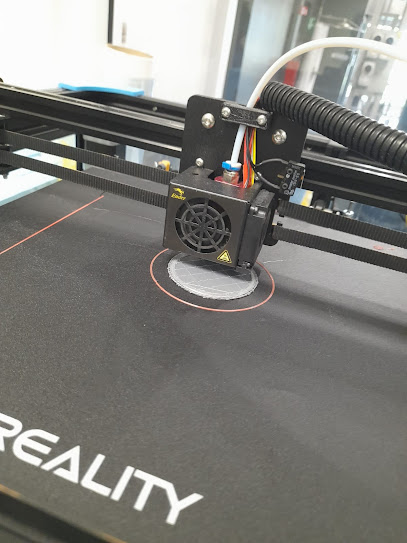
Once all the designs were finished, we needed to print
them out/ laser cut them.
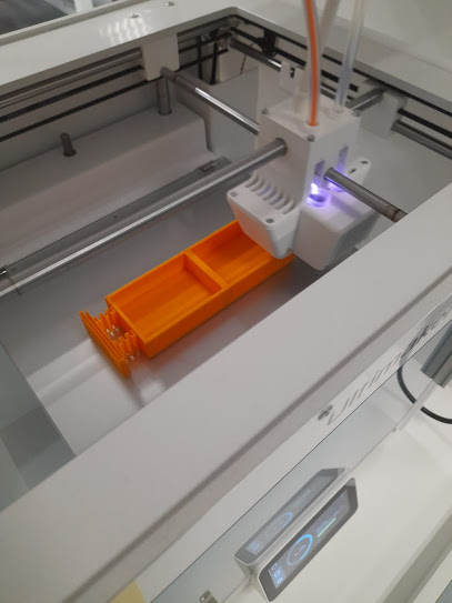
Components that were 3D Printed:
-
Cup
Holder
-
Stirrer
-
Cup
-
Tea Leaf
Holder
Components that were Laser Cut:
-
Electronics
Holder
-
Support


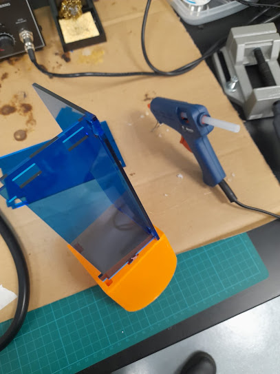


After all components were produced, it was time for the
assembly.
Since acrylic was used for the parts that were laser cut, acrylic glue had to be used to allow them to stick, rather than the conventional hot glue gun. However, for gluing acrylic to the 3D printed components, hot glue gun was sufficient. Of course, the glue was only to provide stability to the overall structure of the product. The connections between components were through joineries.
Once the overall structure was complete, the electrical components were added into the tea maker body, with the stirrer being attached to the servo motor.
Part 4. Wiring (done by Xavier)
Link to Blog: https://cp5070-2021-2b01-group2-xavier-chua.blogspot.com/2022/02/cpdd-blog-project-development.html
Part 5. Coding (done by Nick)
Link
to Blog: https://cp5070-2021-2b01-group2-nick.blogspot.com/2022/02/project- development.html
Final Product


4. Problems
and solutions
We encountered several problems during the entire process
of the project.
Firstly, when we were performing the 3D printing, we discovered
that the Electronics Holder we had intended to use was printed too small. Thus,
we redesigned the entire section to be bigger, however, due to its length, we
had to laser cut instead.
Next, some of the joineries for the 3D printed parts were
wider than expected and did not fit through the holes, thus there was no way
for them to connect to one another. Our solution was to redesign the connection
holes to be bigger to allow for more leeway, so that there is extra space for
the joineries to fit in when it is 3D printed. However, due to several changes
to the dimensions to the design, these components were laser cut instead.
After laser cutting, we realized that we did not redesign
the holes of these components, therefore the holes were too big for the
joineries. The solution was to use glue to stick the loose areas together
Thirdly, when performing the wiring for the different electrical
components, we found that the wires would disconnect easily, causing our
circuit to be open and incomplete. This was a major disruption in our progress
as we had to constantly go back and reconnect the wires, which resulted in a
lot of time being wasted. Our solution was to keep the wires connected together
as a bunch, instead of pulling them apart and separating them. This helped to
prevent the wires from becoming undone.
Lastly, during the assembly process, we realized that the
hot glue gun that we initially planned to use for connecting the parts together
would not work for acrylic pieces. After consulting the Technical Executives at
W319, we used a different type of glue, an acrylic glue that was more suitable
for gluing different pieces of acrylic together. However, this also led to
another minor problem, as the glue applied was not sufficient, causing our tea
maker to fall apart easily. This was resolved by returning to W319 to reinforce
the glue. The parts held on together more tightly after regluing, especially
because we had applied more glue in the second round to reinforce the adhesion.
Other Limitations and Shortcomings
1. Nick encountered difficulty placing the wired
electrical components into the electronics compartment all at once. This was
because all the walls of the electronics compartment were glued together at a
slight angle, thus putting in the breadboard and Arduino Maker-Uno board
directly inside with the wiring connected was difficult.
Workaround: He disconnected all the wires first, placed
the breadboard and Arduino Maker-Uno board inside by tilting it at an angle,
then reconnected all the wires to the electrical components.
Possible Improvement: We could design the tea maker to be
longer in terms of its breadth. This would make placing the electrical
components wired to the breadboard and Arduino Maker-Uno board easier.
2. The stirrer length was too short, thus when the cup
was fully filled with water, it was only partially submerged under the water.
The partially submerged stirrer would not be able to mix the water and tea
easily.
Workaround: We placed a small piece of acrylic under the
cup, so that the cup would be more elevated, and the stirrer would be able to
be fully submerged under the water.
Possible Improvement: The stirrer length can be
increased. Alternatively, we can increase the height of the cup so that it can
be filled with more water.
3. There was no space for us to install the LCD Display
at the front of the tea maker. Without a place to put the LCD Display, our LCD
Display would dangle away at the side, and potentially be disconnected due to
its weight dragging the connecting wires apart.
Workaround: We balance the LCD Display on top of the tea
maker wall. This ensured that our wiring would not get disconnected, and our
LCD Display would function as per normal.
Possible Improvement: We can design a separate piece to
be laser cut for the LCD Display to rest on. This piece will act as a platform
for the LCD Display.
4. There was no
space in the back for the Arduino cable to fit through to connect to the power
source. Without a power source, our tea maker was unable to function.
Workaround: We removed the cover piece so that the Arduino
cable would be able to connect to the power source.
Possible Improvement: We can design a small slot on the
back plate for the cable to pass through, so that it can connect to a power
source without having to remove the cover piece.
Lastly, some other potential improvements that we can
make are including a speaker for the buzzer, so that the alarm sounds emitted
by the buzzer to notify the tea’s completion can be amplified to reach its user
who may be in another room. We can also code the buzzer to emit different tunes
at different timings, as the code currently used only contains one sound file.
This means that even though the Arduino board was programmed to buzz at
different timings, the buzzer would still emit the same soundtrack at each
timing, thus there is no way for the user to know if their tea has actually
finished brewing or is just past a certain timing.
5. Project Design Files as downloadable files
The link to download the files can be found here (created by Nick):
https://drive.google.com/drive/folders/1Hpg3Z0ATptPvXfuOlwKZuCQXjBYVSNz2?usp=sharing


Comments
Post a Comment